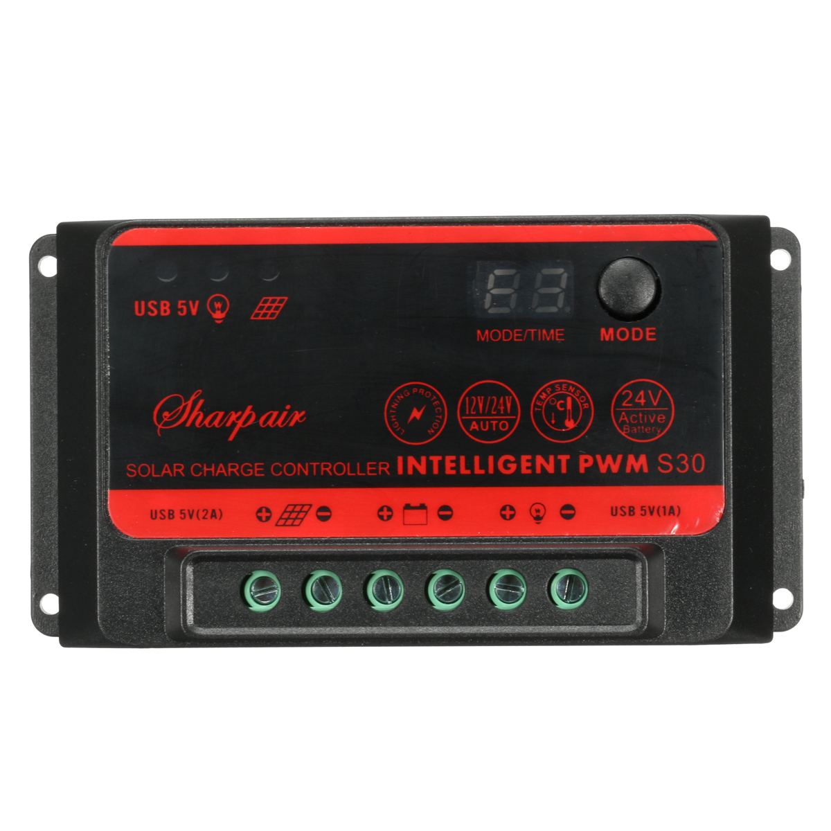
Features:
1.Micro-computer CPU program control, PWA intelligent SOC control circuit.
2.DC5V 2A output with double USB output interface
3.With protections for lightening protection, over-charging, and over current
4.Double LED digital tube display.
5.Automatic identification for 12V and 24V storage battery
6.Battery display, light control&time delay functions
7.24V battery active program: (screen flashing will display “24”, unit the battery’s voltage restores to be normal. Note: if it’s a 12V battery supply, this function is forbidden to use, to avoid battery damage. This active program function is only for 24V battery supply which has not been used for a long time, and is identified as 12V battery because the voltage is too low.)
Applicable: solar power generation system; Solar power generation system for farming; Solar power street lights; Solar power garden lights; Solar power advertising board; Intelligent home products; Solar power traffic light, etc.
Specification:
| Product name |
Smart solar controller |
Current rating |
30A |
| Model |
10A/20A/30A |
System Voltage |
12V/24V automatic identification |
| Power saving mode |
Yes |
System output |
12V/24V; 5V |
| Powe diaplay |
Yes |
Circuit pressure drop |
<0.26V |
| Light control&delay time |
Yes |
Over rechargig voltage |
14.6V; 14.6V*2/24V |
| Product size |
128*70*26mm |
Over diachargig voltage |
10.8V/12V; 10.8V*2/24V |
| Control mode |
PWM pulse debug mode |
Return voltage of over diacharging |
12.2V/12V; 12.2V*2/24V |
Package includes:
1 x Solar Controller
1 x User Manual
Details pictures:


Installation and usage:
1.To fix the controller well
2.Get cables prepared. It is suggested to multi copper insulating cables. Check the length of the cables firstly. Use as less cables and possible to reduce the power consumption after confirm the installation position.
3.Connect “-” pole of the storage battery of the controller firstly, and then connect “=” pole. Please be sure to avoid these 2 poles to touch each other, to prevent from damaging the battery and other parts. After connection, the display screen and the corresponding battery indicator of will light. If not, please check if the connection is correct.
4.Connect the solar power generation board. Firstly connect the “+” and “-” poles separately to the solar power battery board. After connection,leave the solar board outdoor with sunlight, then the recharging indicator will light. If not, please check the connection is correct
5.Overloading connection: to connect the overloading to the corresponding overloading output of the controller. Please do not mistake the connection of the “+” and “-” poles, in case to damage all the equipments.
6.Installation of the solar power generation board. To point at 12 clock direction of the sun at noon. The light collection side of the solar power generation board face to the south, keep a tilt angle of 45 degree to the ground to the ground, to be sure the board can burned by sun for a whole day
Note: the controller must be installed in a position away from rain and snow. The cables of the solar power board and overloading follow “U” shape under the controller and fix well. Please be sure no rain will enter the controller. Fasten all screws of all cables ports, in case that the cables will get loose and cause a bad connection
Warm:
The battery connection must be firstly installed, and them connect the solar power generation board. If several wrong installations happen, it might burn and damage the controller
Please do not use other power supply to replace the solar power board to test the system, otherwise it will damage the controller.
Basic operation:
1.System connection. Please check the connection drawing and read the installation and usage instruction on it.
2.After connection, the system will switch on automatically. It will detect and identify the 12V or 24V battery supply. When it detects a 12V battery supply, the screen will flash “12”. When it is a 24V battery supply, it will flash”24”. If no any operation is done, the screen will be a battery display after the system booting.
3.Short press [MODE] to enter light control&time delay.
4.Long press [MODE] button for 6 seconds, the system will initialize.
5.Long press [MODE] for more than 20 seconds, the system will enter 24V battery active program
Note: After booting, the system will automatically identify the battery supply. After any button press operation, it will enter other corresponding display. If the digital tube displays a number between 0-15(including 0 and 15), it means the system already enters the light control and time delay function. If want to exit this function, please long press[MODE] button for 6 second
The display will be off after seconds to save power consumption. After the display is off, short press [MODE] button, setting up value is available to check.


 Availability:
  Shipping: Free Airmail


Reviews
There are no reviews yet.