Description:
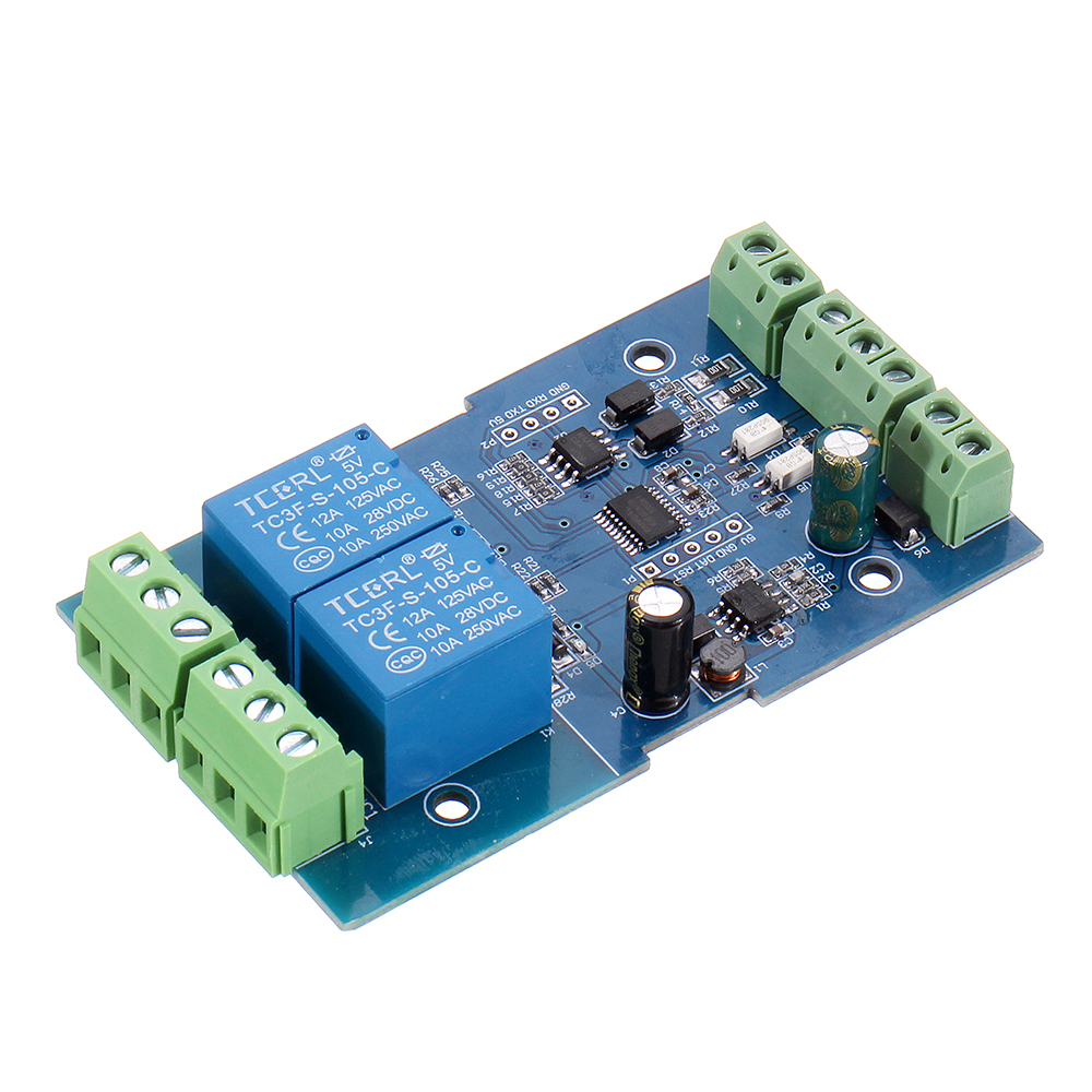
LC 2 channel Modbus relay module equipped with mature and stable 8-bit MCU and RS485 level communication chip, adopt standard MODBUS RTU format RS485 communication protocol. It can realize 2bit input signal detection and 2-bit relay output. It can be used for digital detection or power control occasions.
Features:
1. Support Modbus RTU protocol
2. Support RS485/TTL UART interface
3. Output indicator in multi-mode
4. The address can be set
5. Support input reverse connection protection
6. Relay switch output
7. Support parameter memory function
Parameters:
1. Item name: Dual Modbus Relay Module
2. Work voltage: DC 7V~24V
3. Baud rate: 4800/9600/19600bps(default 9600bps)
4. Optocoupler input signal: DC 3.3V~30V
5. Set address: 1~255
6. Relay control mode: ON/OFF, Delay_ON, Delay_OFF mode
7. Delay time: 0~6553.5s
8. Load: AC 250V 10A or DC 28V 10A
9. Protocol: Modbus RTU
10. Interface: RS485/TTL UART
11. Control channel: 2channel
12. Operating Temperature: -20℃~85℃
13. Operating Humidity: 5%~95%RH
14. Module Size: 85 x 49 x 19mm
Modbus RTU :
1. Suppose the device address is 0xFF so return 00 10 00 00 00 01 02 00 FF EB 80 and the 9th byte is device address.
2. Turn ON CH_1 Relay (Normal Mode):
Send: FF 05 00 00 FF 00 99 E4
Return: FF 05 00 00 FF 00 99 E4
Note_1: The 3rd and 4th byte are relay addresses. So it can be 0x0000, 0x0001, 0x0002, 0x0003.
Note_2: The 5th and 6th byte are relay data. 0xFF00 means turn ON relay and 0x0000 means turn OFF relay.
3. Turn OFF CH_1 Relay(Normal Mode):
Send: FF 05 00 00 00 00 D8 14
Return: FF 05 00 00 00 00 D8 14
4. Turn ON CH_2 Relay(Normal Mode):
Send: FF 05 00 01 FF 00 C8 24
Return: FF 05 00 01 FF 00 C8 24
5. Turn OFF CH_2 Relay(Normal Mode):
Send: FF 05 00 01 00 00 89 D4
Return: FF 05 00 01 00 00 89 D4
6. Turn ON All relays:
Send: FF 0F 00 00 00 08 01 FF 30 1D
Return: FF 0F 00 00 00 08 41 D3
7. Turn OFF All relays:
Send: FF 0F 00 00 00 08 01 00 70 5D
Return: FF 0F 00 00 00 08 41 D3
8. Set device address to 0x01:
Send: 00 10 00 00 00 01 02 00 01 6A 00
Return: 00 10 00 00 00 01 02 00 01 6A 00
Note: The 9th btye is device address.
9. Set device address to 0xFF:
Send: 00 10 00 00 00 01 02 00 FF EB 80
Return: 00 10 00 00 00 01 02 00 FF EB 80
10. Read device address:
Send: 00 03 00 00 00 01 85 DB
Return: 00 03 02 00 FF C5 C4
Note: The 5th btye is device address.
11. Read relay :
Send: FF 01 00 00 00 08 28 12
Return: FF 01 01 01 A1 A0
Note: The 4th means which one relay. 0 means OFF and 1 means ON.
12. Read optocoupler input staturs:
Send: FF 02 00 00 00 08 6C 12
Return: FF 02 01 01 51 A0
Note: The 4th means which one input. 0 means low level signal input and 1 means high level signal input.
13. Set baud rate 4800bps:
Send: FF 10 03 E9 00 01 02 00 02 4A 0C
Return: FF 10 03 E9 00 01 C5 A7
Note: The 9th btye is baud rate value. 0x02 is 4800bps. 0x03 is 9600bps. 0x04 is 19200bps.
14. Set baud rate 9600bps:
Send: FF 10 03 E9 00 01 02 00 03 8B CC
Return: FF 10 03 E9 00 01 C5 A7
15. Set baud rate 19200bps:
Send: FF 10 03 E9 00 01 02 00 04 CA 0E
Return: FF 10 03 E9 00 01 C5 A7
16. Turn ON CH_1 Relay(2S Flashing Mode):
Send: FF 10 00 03 00 02 04 00 04 00 14 C5 9F
Return: FF 10 00 03 00 02 A4 16
Note_1: The 3rd and 4th byte are relay addresses. So CH1~CH4 can be 0x0003, 0x0008, 0x000D, 0x0012.
Note_2: The 10th and 11th byte are delay time in second. The delay time is 0.1s. The relay will OFF after delay time. So the delay time in this is: 0x0014*0.1=2S.
17. Turn OFF CH_1 Relay(3S Flashing Mode):
Send: FF 10 00 03 00 02 04 00 02 00 1E A5 99
Return: FF 10 00 03 00 02 A4 16
Note: Relay will ON after delay time. So the delay time in this is: 0x001E*0.1=3S.
Package includes:
3 x Dual Modbus Relay Module


 Availability:
  Shipping: Free Airmail


Reviews
There are no reviews yet.