Description:
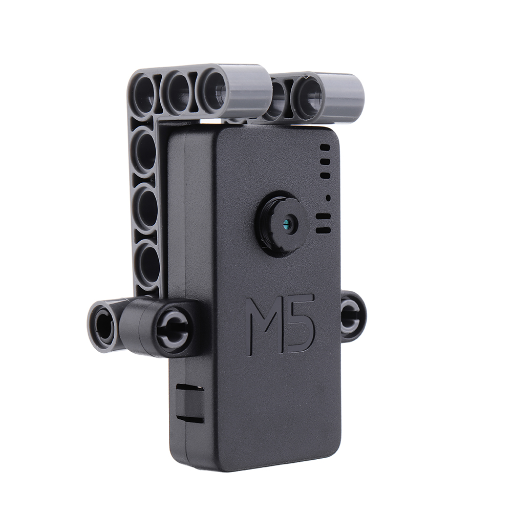
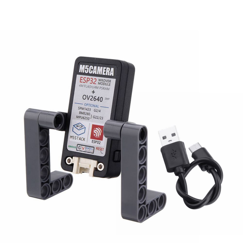
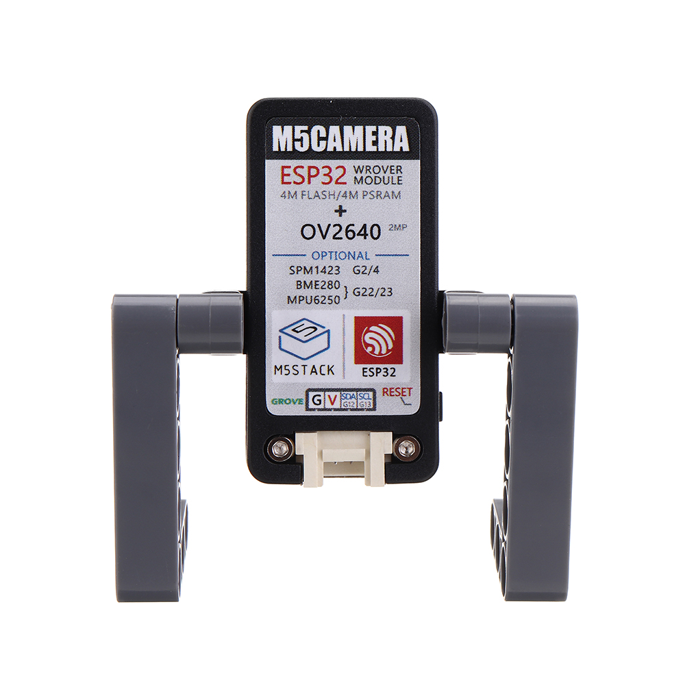
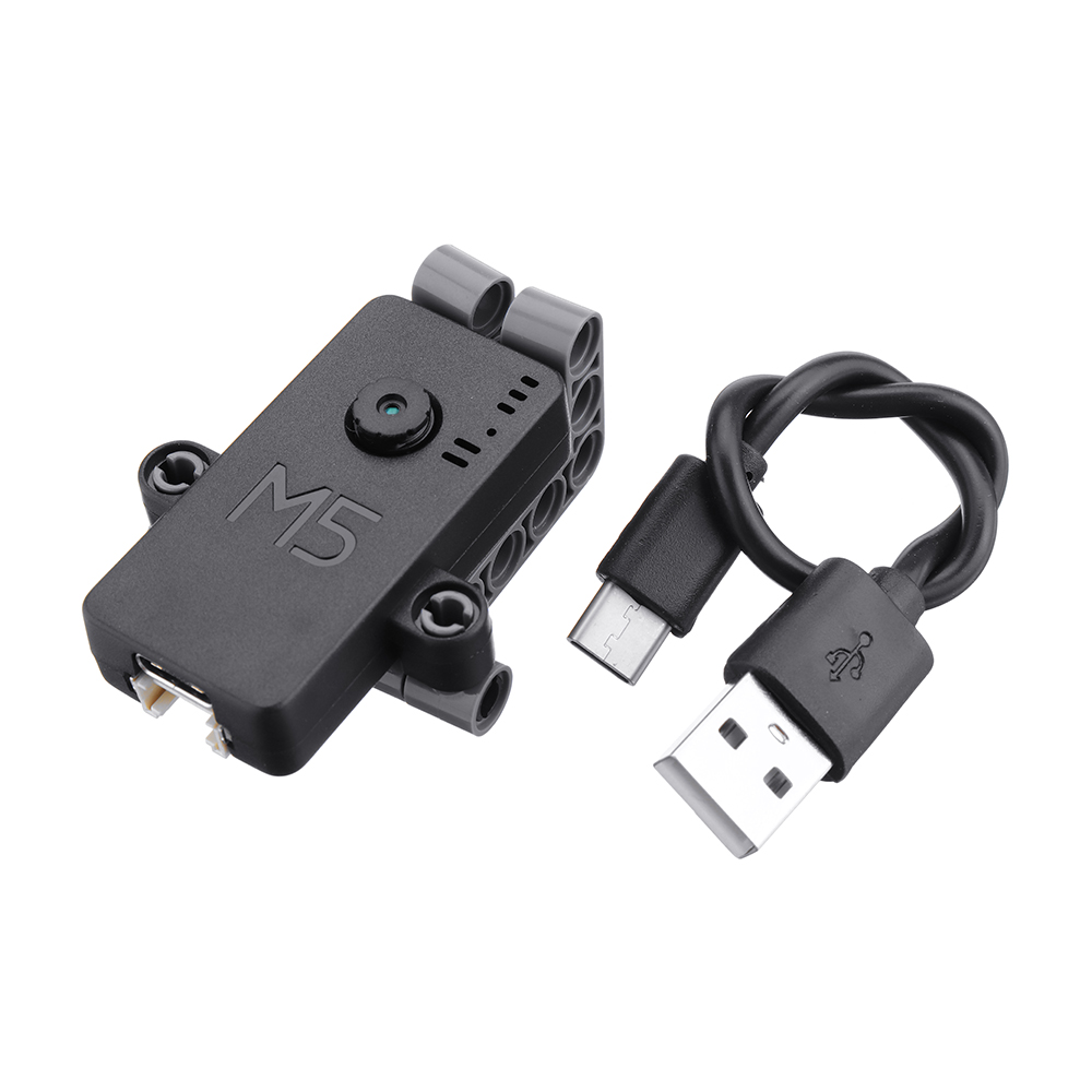
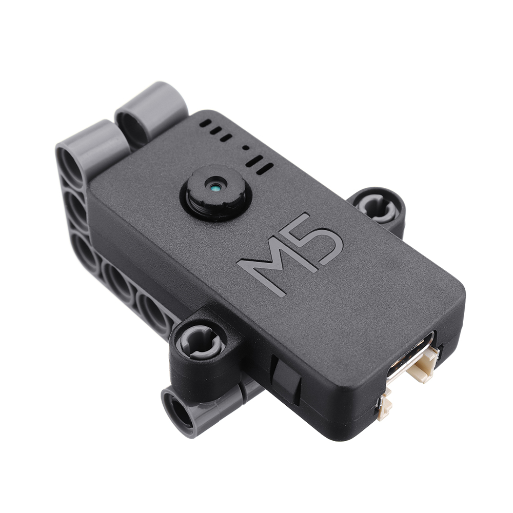
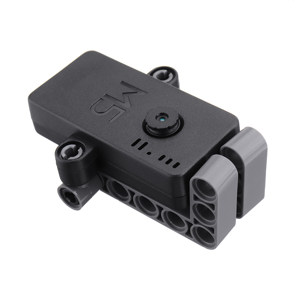
M5Camera is a development board for image recognition. It features an ESP32(4M Flash + 520K RAM) chip and 2-Megapixel carmera(OV2640).M5Camera offers plenty of storage, with an extra 4 Mbyte PSRAM. It also supports image transmission via Wi-Fi and debuging through USB Type-C port.
The hardware comes preloaded software, programmed by ESP-IDF. It is an application to run Wi-Fi camera. The output image is size 600*800, since it’s 2-Maga camera, you sure can optimize the software to output the maximum size of photos.
What this software can do?
Power the board via USB type-C or GROVE
Use your phone to Wi-Fi scan an AP name start with ‘m5stack-‘ and click to connect this AP.
Open up web browser on your phone and visit 192.168.4.1
Then here comes the picture. Video is about 5-6 frames per senconds. not super fast.
The hardware also comes with some reserved weld pad, just in case you want put these chips back on board.
– 9-axis gyroscope (MPU6050)
– pressure sensor (BME280)
– Analog MIC (SPQ2410)
– Lipo Battery power pins
Note:
M5Camera is named differently when different hardware is selected. They follow the rules below.
M5Camera_#_#… means optional hardware name follows “M5Camera”.
If configured with MPU6050, will be named M5Camera_6050
If also configured with microphone, will be named M5Camera_6050_MIC
If also configured with BME280, will be named M5Camera_6050_MIC_BME280
Features:
1. ESP32 module features
– Integrated dual-core Tensilica LX6
– Up to 240MHz clock frequency
– 4MB internal RAM
– 4MB Flash memory
– Integrated 802.11 BGN WiFi and dual mode Bluetooth (Classic Bluetooth and BLE)
– Hardware encryption (AES, SHA2, ECC, RSA-4096)
2. CP2104 USB to serial port
3. OV2640 camera driver
– Output format (8-bit):
YUV(422/420)/YCbCr422
RGB565/555
8-bit compressed data
8-/10-bit Raw RGB data
– Maximum transfer rate of the picture
UXGA/SXGA: 15fps
SVGA: 30fps
CIF: 60fps
– Scan mode: Progressive
4. Camera features
– CCD size: 1/4inch
– Visual range: 78 degree
– Maximum pixel: 200W
Package Included:
1 x Type-C USB
1 x M5Camera Unit
1 x Instruction Manual
PinMap:
| Interface |
Camera Pin |
M5Camera(A model) |
| SCCB Clock |
SIOC |
IO23 |
| SCCB Data |
SIOD |
IO25 |
| System Clock |
XCLK |
IO27 |
| Vertical Sync |
VSYNC |
IO22 |
| Horizontal Reference |
HREF |
IO26 |
| Pixel Clock |
PCLK |
IO21 |
| Pixel Data Bit 0 |
D2 |
IO32 |
| Pixel Data Bit 1 |
D3 |
IO35 |
| Pixel Data Bit 2 |
D4 |
IO34 |
| Pixel Data Bit 3 |
D5 |
IO5 |
| Pixel Data Bit 4 |
D6 |
IO39 |
| Pixel Data Bit 5 |
D7 |
IO18 |
| Pixel Data Bit 6 |
D8 |
IO36 |
| Pixel Data Bit 7 |
D9 |
IO19 |
| Camera Reset |
RESET |
IO15 |
| Camera Power Down |
PWDN |
see Note 1 |
| Power Supply 3.3V |
3V3 |
3V3 |
| Ground |
GND |
GND |
GROVE Interface
| Grove |
M5Camera(A model) |
| SCL |
IO13 |
| SDA |
IO12 |
| 5V |
5V |
| GND |
GND |
LED Interface
| LED |
M5Camera |
| LED_Pin |
IO14 |
The following tables are Reserved Chip Interfaces
BME280 Interface
It’s IIC address is 0x76.
| BME280 |
M5Camera |
| SCL |
IO23 |
| SDA |
IO22 |
MPU6050 Interface
It’s IIC address is 0x68.
| MPU6050 |
M5Camera |
| SCL |
IO23 |
| SDA |
IO22 |
MIC(SPM1423) Interface
| MIC(SPM1423) |
M5Camera |
| SCL |
IO2 |
| SDA |
IO4 |
NOTE:
Camera Power Down pin does not need to be connected to ESP32 GPIO. Instead it may be pulled down to ground with 10 kOhm resistor.


 Availability:
  Shipping: Free Airmail


Reviews
There are no reviews yet.