Description:
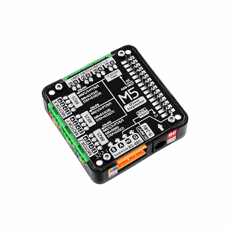
StepMotor Driver is adapted to M5 core series, the HR8825 chip solution provides a 3-way bipolar stepper motor control interface. You can implement independent control or multi-axis motor linkage after this module is stacked with M5 core series of the internal ESP32 generates signals directly to the driver chip.
This module integrated TCA9554 IO expansion chip provides 4 sets of input signal terminals + 3 sets of stepper motor subdivision control + 1 set of drive chip enable control, through the I2C interface control, can monitor and control the 8 expansion IO state, as well as for external limit switch, dynamic subdivision adjustment, motor braking. Integrated PWR485 communication interface (RS485 + 9-24V power input) and DC-JACK, which can be used for communication and more flexible power supply. Download the UIFLOW and you’re ready to go!
With ESP32-GRBL firmware, web control. It can be easy to configure signal output and very useful when you need to position something very accurately. such as:printers, robotic arms, etc.
Note:
It is forbidden to plug or unplug the motor when it is powered on. All operations should be performed after the device is powered off to avoid damage to the module.
Product Features:
Three-axis HR8825 stepper motor driver
Suitable for bipolar stepper motors
With current regulating potentiometer per circuit, drive current up to 1.5A
Support various subdivision modes, up to 1/32 STEP subdivision
Multiple signal input interfaces
PWR485 communication interface (RS485 + 9-24V power input)
DC-JACK terminal input (9-24V)
Built-in DCDC, integrated 9-24V to 5V circuit
Development platform.
Arduin0, UIFlow
Specification:
|
Specifications
|
parameters
|
|
Stepper motor driver chip
|
HR8825
|
|
IO Expansion Chip
|
TCA9554
|
|
Support for segmentation
|
FULL、1/2、1/4、1/8、1/16、1/32
|
|
Maximum drive current per channel
|
1.5A
|
|
Input Signal Terminal Specifications
|
2.54-2P
|
|
Motor terminal specifications
|
2.54-4P
|
|
RS485 terminal specifications
|
3.96-4P
|
|
Net weight
|
40g
|
|
Gross weight
|
60g
|
|
Product Dimensions
|
54.2 * 54.2 * 13.2mm
|
|
Packaging size
|
95 * 65 * 25mm
|
Package Included:
1 x StepMotor Driver
4 x 2.54-2P terminals
3 x 2.54-4P terminals
1 x 3.96-4P terminals
Applications:
Printers
Scanners
CNC engraving machine control
Motion Module Control
Microstep truth table
|
M2
|
M1
|
M0
|
Resolution
|
|
0
|
0
|
0
|
FULL
|
|
0
|
0
|
1
|
1/2
|
|
0
|
1
|
0
|
1/4
|
|
0
|
1
|
1
|
1/8
|
|
1
|
0
|
0
|
1/16
|
|
1
|
0
|
1
|
1/32
|
|
1
|
1
|
0
|
1/32
|
|
1
|
1
|
1
|
1/32
|
TCA9554 IO Expansion Chip
I2C Addr: 0x27
Use register 0x00 when reading status
Use register 0x01 when writing status
Configure the corresponding bit in register 0x02 to 1 to achieve polarity inversion, and configure it to 0 to not reverse Turn to
The corresponding bit in the register 0x03 is configured as 1 for input mode, and 0 for output mode.
The pin relationship corresponding to the above register bytes is shown in the table below.
|
Bit
|
Desc
|
R/W
|
|
7
|
P7 Subdivision adjustment bit M0
|
R/W
|
|
6
|
P6 Subdivision adjustment bit M1
|
R/W
|
|
5
|
P5 Subdivision adjustment bit M2
|
R/W
|
|
4
|
P4 DRV EN driver chip enable
|
R/W
|
|
3
|
P3 input signal 3
|
R/W
|
|
2
|
P2 input signal 2
|
R/W
|
|
1
|
P1 input signal 1
|
R/W
|
|
0
|
P0 input signal 0
|
R/W
|
Related Links
Pin Mapping
HR8825
|
CORE
|
G16
|
G12
|
G15
|
G17
|
G13
|
G0
|
|
HR8825 X
|
STP X
|
/
|
/
|
DIR X
|
/
|
/
|
|
HR8825 Y
|
/
|
STP Y
|
/
|
/
|
DIR Y
|
/
|
|
HR8825 Z
|
/
|
/
|
STP Z
|
/
|
/
|
DIR Z
|
RS485
|
CORE
|
G34
|
G26
|
GND
|
|
RS485
|
TX
|
RX
|
GND
|
TCA9554
|
CORE
|
G21
|
G22
|
5V
|
GND
|
|
TCA9554
|
SDA
|
SCL
|
VIN
|
GND
|
Schematics:
Example
Note:
ESP32-GRBL & WEB-UI The program requires the use of ESP32 board management 1.0.3 version, which is higher It may not compile normally. Please refer to
ESP32-GRBL-WIKI for instructions on use and WEB-UI control


 Availability:
  Shipping: Free Airmail


Reviews
There are no reviews yet.